 |
 |
 |
 |
 |
 |
 |
 |
||||||
|
|
|
||||||||||||
| |
|
 |
 |
||||||||||
|
|||||||||||||
 |
|||||||||||||||||||||||||
 |
|
||||||||||||||||||||||||
 |
|
||||||||||||||||||||||||||||||||
 |
Flexural strengthening |
||||||||||||||||||||||||||||||||
|
|
|||||||||||||||||||||||||||||||||
|
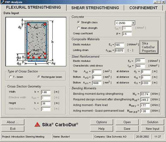
Reinforced concrete elements, such as beams, slabs and columns, may be strengthened in flexure through the use of FRP composites epoxy-bonded to their tension zones, with the direction of fibres parallel to that of high tensile stresses (member axis). The calculations described address both the Ultimate Limit State (ULS) and the Serviceability Limit State (SLS). Input: |
|||||||||||||||||||||||||||||||||
 |
|||||||||||||||||||||||||||||||||
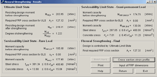
| Ultimate Limit State
The calculations are based on the assumption that one of the following two desirable failure modes govern the behaviour: |
|||||||||||||||||||||||||||||||||
|
|||||||||||||||||||||||||||||||||
 |
|||||||||||||||||||||||||||||||||
|
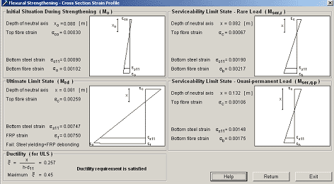
The first step in the calculations is to find the initial strain,
|
|||||||||||||||||||||||||||||||||
 |
|||||||||||||||||||||||||||||||||
Serviceability Limit StateFor the SLS (Serviceability Limit State), the analysis of the critical cross section is performed, according to EC2, for the two possible load combinations:
For the case of Rare Load the calculations are performed as in the case of the ULS, with the following modifications:
For the case of Quasi-permanent Load the calculations are performed as in the case of the ULS, with the following modifications:
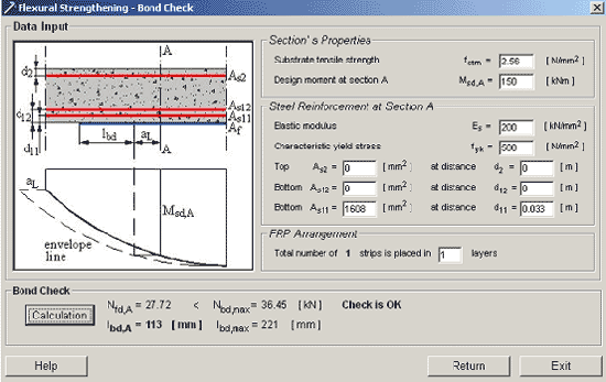
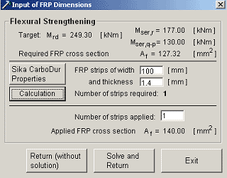
Bond checkFor user-defined dimensions of the FRP cross section
geometry (n strips of width bf and thickness tf
placed in m layers, n/m should be an integer if m > 1) the
program calculates the maximum force, Nbd,max, that
can be carried by the total number of strips, and the associated
bond length, lbd,max,before debonding of the external
reinforcement initiates at the ends (anchorage zone).
At each cross section (say A), equilibrium and strain compatibility equations yield the tensile force Nfd,A carried by each strip. If this force does not exceed Nbd,max, then the bond check is verified, that is failure of the anchorage is not expected, provided that the appropriate bond length lbd will be available. The bond length corresponding to Nfd,A is calculated. It was mentioned above that Nfd,A is
the tensile force carried by the FRP. This is calculated by multiplying
the cross sectional area Af by the product of elastic
modulus times strain, Ef
|
|||||||||||||||||||||||||||||||||
| © Sika Services
AG Construction 2002 / bb |


 c replaced
by
  ).
).