 |
 |
 |
 |
 |
 |
 |
 |
||||||
|
|
|
||||||||||||
| |
|
 |
 |
||||||||||
|
|||||||||||||
 |
|||||||||||||||||||||||||
 |
|
||||||||||||||||||||||||
 |
|
||||||||||||
 |
Shear strengthening |
||||||||||||
|
|
|||||||||||||
|
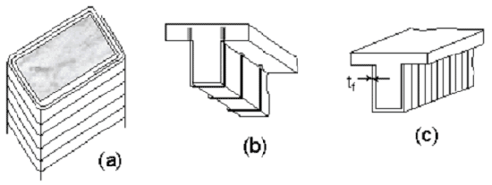
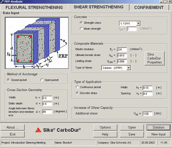
Shear strengthening of RC members using FRP may be provided by bonding the external reinforcement with the principal fibre direction as parallel as practically possible to that of maximum principal tensile stresses, so that the effectiveness of FRP is maximised. For the most common case of structural members subjected to lateral loads, the maximum principal stress trajectories in the shear-critical zones form an angle with the member axis that may be taken roughly equal to 45°. However, it is normally more practical to attach the external FRP reinforcement with the principal fibre direction perpendicular to the member axis. |
|||||||||||||
 |
|||||||||||||
|
|
|||||||||||||
The option "Closed jacket" or "Open jacket"
is selected, depending on the type of strengthening system used.
Shear strengthening of columns where all four sides are accessible
is typically of the closed-type. Moreover, shear strengthening of
T-beams with mechanical anchorage systems that ensure perfect anchorage
of the FRP in the compression zone may be considered of the closed-type
too. This is the case, for instance, with the CarboShear elements,
if sufficient anchorage length is available through the slab. For
these particular elements, if the anchorage length is less than
300 mm, it is recommended to take a solution, calculated by linear
interpolation between "Closed jacket" and "Open jacket",
that is to run the programme for both cases and adopt the value
by linear interpolation. Consult also the technical datasheet and
design recommendation of this product. Input:Vfd is the contribution of FRP to the member's shear
capacity. Ef is the elastic modulus of FRP, b is the
width of the cross section, d is the static (or effective) depth,
The first term (described in eqs. (1.3.3a), (1.3.3b) and (1.3.4)
in the help function) corresponds to FRP fracture (when the member's
shear capacity is reached), hence the use of 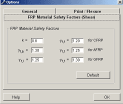
The thickness of FRP required to provide a shear resistance equal to Vfd will be calculated. 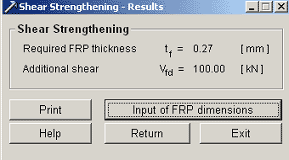
After the input of the effective thickness of the FRP - layer, the number of layers and the effective reinforcing shear capacity can be calculated. 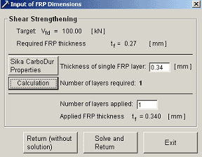 |
|||||||||||||
| © Sika Services
AG Construction 2002 / bb |

 f,e
which is, in general, less than the tensile failure strain,
  is the angle between the principal
FRP fibre orientation and the longitudinal axis of the member,
 f
is the FRP material safety factor. The